
Why Choose a T Beam Welding Line?

Choosing a T beam welding line is a practical decision about consistency, output, and the way a shop handles long structural members. A well-matched line can position the web and flanges, maintain alignment, and weld repeated T sections with less manual handling. In a fabrication shop, small shifts in fit-up can become visible as uneven welds, distortion, or extra correction work. Reliable positioning helps reduce those avoidable variations. That matters.

The right setup also depends on the parts being made. Beam dimensions, steel thickness, production volume, available floor space, and operator skills all shape the equipment choice. A line designed for one product range may not suit frequent changes in size or short production runs. Automation can improve repeatability, but it cannot compensate for poor material preparation or an unsuitable process. It is not magic.

This guide looks at the practical reasons manufacturers consider a T beam welding line, including productivity, weld consistency, labor demands, and process control. It also considers limitations and questions buyers should ask before investing. Cycle-time figures and advertised capacity deserve careful checking against real parts and working conditions. That part is easy to underestimate. A useful choice is not simply the most automated one; it is the line that fits the work, the team, and the shop’s actual production needs.
Why Choose a T Beam Welding Line?

What Is a T Beam Welding Line?

Why Choose a T Beam Welding Line?

What Is a T Beam Welding Line?

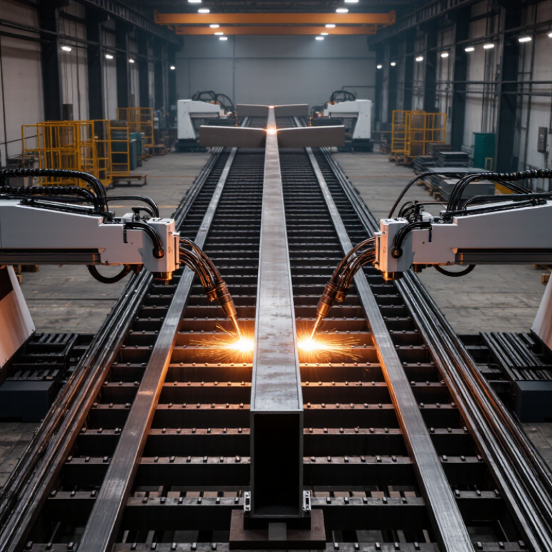
A T beam welding line is a production setup for joining a vertical web plate to a horizontal flange plate. Together, these parts form a T-shaped structural member. The line may include plate positioning, clamping, tack welding, main welding, and material handling equipment. Each stage helps keep the web centered and the flange square. Small alignment errors can become visible across a long beam.

Depending on the design, operators may use automatic welding equipment and adjustable fixtures to produce beams in different sizes. Sensors and controls can help maintain travel speed and welding settings, but they do not replace inspection.

That matters.

Weld quality still depends on clean plate edges, suitable parameters, and careful setup. A line can improve repeatability and reduce repeated manual handling, especially when many similar beams are required. Yet changeovers take time, and poorly matched settings may cause rework.

Not quite effortless.

Before choosing a system, manufacturers should consider beam dimensions, plate thickness, production volume, and the space available on the shop floor. Those practical limits shape what the line can reliably produce.

How Does the Welding Process Work?

Why Choose a T Beam Welding Line?

How Does the Welding Process Work?

A T-beam line starts by positioning the web vertically against the flange, then clamping both pieces to hold the required angle. Tack welds secure the joint before the main weld pass. Many lines use submerged arc welding (SAW) for the long seams: an electric arc melts the joint beneath granular flux, shielding the molten metal. The beam moves steadily through the welding station. Small alignment errors at this stage can show up later as uneven legs or distortion.

After welding, operators check dimensions and inspect the seams before straightening the beam if needed. Automated handling can make repeated passes more consistent, but it does not remove the need for process checks. The International Federation of Robotics reported 4,281,585 industrial robots operating worldwide in 2023, in its World Robotics 2024 report. That figure reflects industrial automation broadly, not T-beam lines specifically. The awkward part is that a steady weld may still leave a beam needing correction.

Tips: Keep the web and flange clean, verify fit-up before tack welding, and monitor heat input. Record any recurring distortion; it may point to an alignment or sequence issue.

Why Choose a T Beam Welding Line? — How Does the Welding Process Work?
Stage What Happens Typical Equipment or Method Why Use a Welding Line? Key Quality Checks
1. Plate preparation The flange and web plates are cut to the required dimensions. Edges and surfaces are cleaned where needed. Plate cutting equipment, measuring tools, and surface-cleaning tools. Consistent preparation helps parts fit correctly and supports repeatable weld setup. Verify plate dimensions, edge condition, and cleanliness against the job drawings and welding procedure.
2. Web and flange positioning The web is positioned on the flange to form a T-shaped section, with alignment and orientation set for the required design. Positioning rollers, locating guides, clamps, or fixtures. Guided positioning helps maintain straightness and reduces manual alignment variation. Check web position, squareness, and fit-up along the length.
3. Tack welding Short welds temporarily hold the web and flange together before the continuous welds are made. Manual or mechanized tack welding using a process suitable for the material and approved procedure. Secure fit-up helps prevent parts from shifting as the beam moves through the line. Confirm tack welds are sound, correctly placed, and compatible with the production weld sequence.
4. Main seam welding Continuous fillet welds join the web to the flange. Depending on the line configuration, the two sides may be welded simultaneously or in sequence. Mechanized welding; submerged arc welding is commonly used for long, straight seams, while other processes may be selected for the application. Mechanized travel and controlled welding parameters can improve consistency and reduce repetitive manual work. Monitor the approved welding parameters, seam continuity, weld size, and visible surface condition.
5. Cooling and handling The welded section is allowed to cool as required and is transferred without damaging the welds or distorting the beam. Roller conveyors, supports, and material-handling equipment. Coordinated movement helps maintain production flow and supports safer handling of long sections. Check for handling damage and follow the specified sequence before further processing.
6. Straightening Where required, the beam is corrected to meet the specified straightness and shape tolerances after welding. Mechanical straightening equipment selected for the section and required correction. Integrated straightening can reduce separate handling steps and help prepare the beam for downstream work. Measure straightness and relevant dimensional tolerances using the project’s inspection method.
7. Inspection and finishing The completed T beam is inspected, identified, and prepared for the next fabrication or coating operation. Visual inspection and, when required, specified non-destructive testing and dimensional measurement. A defined inspection point supports consistent acceptance and traceability. Assess weld appearance, dimensions, and any required inspection results against the drawings, codes, and project requirements.

Welding process, sequence, and operating parameters depend on the base material, plate thickness, joint design, applicable code, and approved welding procedure. Confirm project-specific requirements before production.

What Advantages Does a T Beam Welding Line Offer?

Why Choose a T Beam Welding Line?

What Advantages Does a T Beam Welding Line Offer?

A T beam welding line can make fabrication more consistent by controlling positioning, clamping, and weld travel. The web and flange stay aligned as they enter the welding station, reducing repeated measuring and manual repositioning. That matters. Small alignment errors can cause uneven joints, extra correction work, or visible distortion after cooling.

A coordinated line also helps maintain a steady production rhythm. Operators can prepare the next beam while another moves through welding, cutting idle time between jobs. For example, repeatable clamps can hold long sections in place while welders follow defined parameters and inspection points. Less handling can mean fewer opportunities to disturb a fit-up.

Still, automation is not magic.

The best results depend on suitable fixtures, sound procedures, and routine checks on weld quality and beam straightness. Different thicknesses or profiles may need setup changes, so a line can be less flexible than a simple manual station. That trade-off is easy to overlook. Careful trial runs can reveal where heat input causes distortion, giving the team a chance to adjust sequencing before full production.

Where Are T Beams Commonly Used?

Fabricated steel T beams are used where a vertical web and horizontal flange provide useful strength without the bulk of a full I section. In commercial buildings, they can support mezzanines, roof framing, floor edges, and transfer members. On a jobsite, that may mean a beam above a loading bay or beneath a narrow maintenance platform. Fit matters. Their appeal is practical, but the section is not automatically the best choice; connections and load direction still govern the design.

Bridge construction is another setting. Steel T sections may serve as cross-members, deck supports, or stiffeners, depending on the span and structural layout. The American Society of Civil Engineers’ 2021 Infrastructure Report Card counted more than 617,000 U.S. bridges, with 42% at least 50 years old. That scale points to continuing inspection and renewal work, though it does not mean every bridge needs T beams.

T beams also appear in industrial buildings, workshops, and port facilities, where platforms and equipment supports must fit around pipes, ducts, and machinery. worldsteel’s World Steel in Figures 2024 places construction and infrastructure at roughly half of global steel demand. The figure describes a broad market, not T-beam usage specifically. Designers should check corrosion exposure, fabrication tolerances, and access for welding before selecting a section. Small details matter. A flange that looks adequate on paper may complicate a connection in the field.

Why Choose a T-Beam Welding Line? Where Are T Beams Commonly Used?

A fabricated T beam is typically made from one web plate and one flange plate joined by two continuous longitudinal welds.

A dedicated T-beam welding line can help produce consistent, repeatable longitudinal welds. T beams are commonly used in bridge and building structures, floor and roof framing, industrial facilities, and shipbuilding. The chart describes a typical fabricated T section; designs may vary.

What Factors Should Guide Your Choice?

Why Choose a T Beam Welding Line?

What Factors Should Guide Your Choice?

Start with the beams you actually make. Record flange width, web height, material thickness, and the range of lengths. A line suited to frequent, repeatable sizes may struggle with short runs or frequent product changes. Check that its clamps and supports hold the work securely without obstructing the weld path. Fit matters.

Next, compare required output with real production conditions. Ask how quickly operators can load and reposition beams, and whether setup time is included in quoted cycle times. Review welding-process compatibility, seam access, control adjustments, and integration with cutting or handling equipment. Floor space and maintenance access matter too. A highly automated line can reduce manual handling, but it may not pay off when demand varies sharply. That trade-off deserves honest scrutiny. Ask for a demonstration using representative parts, not only an ideal sample. Confirm what training, spare parts, and technical support are available after installation.

Tips: Measure your largest and smallest beams before requesting a specification. Bring sample drawings and weld requirements to the discussion. Leave room for future sizes, but avoid paying for capacity you cannot use.
Go to Top