
How Does the Vacuum Brazing Process Work?

How Does the Vacuum Brazing Process Work? The answer begins with two carefully fitted metal parts and a thin layer of brazing filler. The assembly enters a sealed furnace, where air is removed before controlled heating begins. Without much oxygen, surface oxidation is limited. That matters because even a faint film can interfere with the molten filler’s ability to wet the joint.

As the temperature rises, the filler melts while the base metals remain solid. Capillary action draws the liquid into the narrow gap between them. Then the furnace cools the assembly under controlled conditions, allowing the filler to solidify and bond the parts. No flux is normally needed. Still, vacuum alone cannot rescue a poorly designed joint or contaminated surfaces.

A practical summary is: “The furnace controls the atmosphere, but preparation controls whether the joint succeeds.” This is an original editorial statement, not a verified quotation from a named expert; no source for an expert quotation was provided. That distinction matters. Technical articles should not assign invented words or credentials to real people.

In this guide, we’ll examine the equipment, heating cycle, joint preparation, and quality checks behind the Vacuum Brazing Process. Expect details such as tight clearances, clean mating faces, and temperature uniformity across the load. Small variations can matter. Results also depend on the alloy, component geometry, and furnace setup, so process parameters should be validated for each application. Some assemblies are less forgiving than they look. That is worth remembering before a production run.
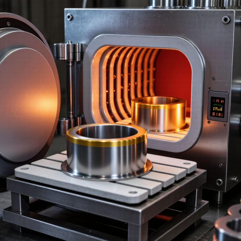
How Does the Vacuum Brazing Process Work?

Preparing the Components and Selecting the Filler Metal

Before a vacuum brazing cycle, prepare each component so the filler metal can reach every joint evenly. Remove oil, fingerprints, machining residue, and oxide using a cleaning method suitable for the base materials. Even a thin film can interfere with wetting. Clean parts should be handled with gloves and stored in a dry area; otherwise, contamination can return before assembly.

Check the joint surfaces for burrs, distortion, and consistent clearance. The correct gap depends on the alloy, filler, and brazing conditions, so use qualified process guidance rather than guessing. Small variations matter. A fixture can hold parts in alignment, but excessive pressure may close the joint and restrict filler flow. That is easy to overlook.

Select a filler metal that wets both base materials and melts below their solidus temperatures. Its composition should also suit the component’s service temperature, corrosion exposure, and mechanical demands. Review the filler’s technical data and verify compatibility with the actual materials. A familiar filler is not automatically the right choice. Test representative assemblies when the joint is critical, then inspect the results; preparation is rarely perfect on the first attempt.

Assembling and Fixturing the Joint

Before vacuum brazing, the mating surfaces must be clean, aligned, and prepared for the chosen filler metal. The joint clearance should remain consistent along the seam. A close fit is not always a better fit: insufficient space can restrict filler flow, while excessive clearance may weaken capillary action. Follow the filler supplier’s recommended range and verify it with measurements, not visual judgment alone. Remove grease, oxide, and machining debris using a suitable cleaning process. Cleanliness matters. Even a small fingerprint can leave residue that affects wetting.

Fixturing keeps parts in position through handling and heating. Use supports that tolerate the furnace environment and do not contaminate the load. Apply only enough force to prevent movement; heavy clamping can obstruct filler flow or stress thin sections. Leave room for parts to expand as temperatures rise. This detail is easy to miss. A setup that feels rigid on the bench may shift or distort in the furnace. For complex assemblies, a dry fit and a trial cycle can reveal support problems before valuable parts are processed. Check that filler placement remains accessible and that the fixture does not trap the joint or block vacuum exposure.

Evacuating the Furnace and Heating the Assembly

A sound vacuum cycle begins before the pump starts. Parts are cleaned, dried, and positioned so the joint remains accessible to molten filler metal. The filler is placed close to the seam, not piled on top of it. Small gaps matter. They help capillary action draw the liquid alloy through the joint.

With the furnace sealed, pumps remove air and moisture from the chamber. Operators watch the pressure gauge and follow the vacuum level specified for the materials and equipment. A pressure reading alone does not prove the parts are clean; oils and trapped residues can still release gas as temperatures rise. Real furnaces are less tidy than diagrams suggest. That is worth remembering.

Once conditions are suitable, the furnace heats the assembly at a controlled rate. This gives the parts time to warm evenly and reduces the risk of distortion or uneven filler flow. Temperature sensors help track the cycle, though their readings may not perfectly match every spot in a densely loaded fixture. Near the brazing temperature, the filler melts while the base metals remain solid. It flows into the narrow joint and forms a bond during the hold period. The assembly then cools under vacuum or a controlled atmosphere, depending on the process. A hurried ramp can save minutes, but it may leave a joint that looks sound and performs poorly.

How Does the Vacuum Brazing Process Work? — Evacuating the Furnace and Heating the Assembly

This illustrative profile shows the furnace being evacuated before the assembly is heated, then held at brazing temperature and cooled. The example pressure and temperature are not universal cycle settings; actual requirements depend on the filler metal, base materials, component design, and furnace load.

Melting the Filler Metal and Forming the Bond

In vacuum brazing, the filler metal melts while the parent components remain solid. The AWS Brazing Handbook defines brazing as joining above 450°C, below the base metals’ melting temperatures. That temperature gap matters: too little heat leaves filler unmelted; too much can distort thin parts. The tricky part? Controlling the joint gap. AWS guidance places typical clearances in the thousandths-of-an-inch range, with the right value depending on filler alloy and process conditions. A gap that looks tiny under a lamp can still change how evenly the molten metal travels.

As the filler liquefies, capillary action draws it through the narrow joint. Vacuum furnace practice helps limit oxidation, so the metal can wet clean surfaces and form a continuous bond. ASM Handbook, Volume 6A, describes atmosphere control as a key factor in brazing quality. Cleanliness still matters. Oil or machining residue can disrupt flow and leave voids, even in a well-controlled furnace. After cooling, the filler solidifies and mechanically joins the parts; diffusion at the interface can also contribute, depending on the materials and cycle. One detail is easy to underestimate: a shiny fillet does not prove the entire hidden seam filled. Sectioning sample joints or using suitable inspection methods can reveal gaps that appearance alone misses.

Cooling the Assembly and Inspecting the Joint

After brazing, the assembly must cool under controlled conditions, often while it remains inside the vacuum furnace. The cooling rate depends on the base metals, filler alloy, and part geometry. A thick plate joined to a thin tube may cool unevenly if the cycle is poorly chosen. That can create stress or distortion.

The wait matters. Opening the chamber too early can expose hot metal to air and cause oxidation. Once the part reaches a safe handling temperature, record its condition and compare key dimensions with the drawing. Look for visible cracks, incomplete fillets, excessive filler, or discoloration near the joint. A shiny fillet is reassuring, but it is not proof of a sound bond. Depending on the part’s purpose, inspection may also include dye penetrant testing, radiography, or a leak test. The method should match the likely defect and acceptance criteria. Keep the furnace cycle and inspection results together; they help trace problems back to a specific run. Even then, inspection has limits. A clean-looking joint can hide an internal flaw, so choosing the right test deserves careful thought.

How Does the Vacuum Brazing Process Work? - Cooling the Assembly and Inspecting the Joint
Process Stage What Is Controlled or Checked Typical Practice Purpose and Evaluation
Cooling begins Furnace temperature and atmosphere After the specified brazing hold, the assembly is cooled in the furnace while vacuum is maintained, or with a qualified inert-gas cooling cycle. Protects hot surfaces from oxidation and keeps the cooling cycle within the approved procedure.
Cooling rate Temperature change through the load Use the rate established for the part, filler metal, base materials, and furnace load. Avoid abrupt cooling unless the process has been specifically qualified for it. Limits thermal gradients, distortion, and stress that could damage the joint or assembly.
Temperature monitoring Load and furnace temperatures Record the furnace cycle using calibrated sensors and the monitoring arrangement specified by the process plan. Confirms the assembly followed the required cooling cycle; acceptance limits are part- and procedure-specific.
Return to safe handling conditions Part temperature and furnace atmosphere Keep the assembly in the protected furnace environment until it reaches the temperature at which the approved procedure permits unloading or atmosphere change. Reduces oxidation risk and helps protect personnel and the assembly during handling.
Visual inspection Joint area and surrounding surfaces Inspect accessible areas for cracks, incomplete filler flow, excessive filler, visible voids, and signs of distortion or contamination. Identifies visible defects; visual inspection alone cannot verify the entire internal joint.
Dimensional inspection Critical dimensions and alignment Measure specified features with suitable calibrated gauges or measuring equipment and compare results with the drawing tolerances. Confirms that cooling or brazing has not caused unacceptable movement or warpage.
Leak testing, when required Joint integrity in sealed assemblies Use the specified method, such as a helium mass-spectrometer test or pressure-decay test, with the acceptance limit defined for the component. Evaluates leakage performance; the appropriate method and limit depend on the design and service requirements.
Non-destructive examination, when required Internal joint features Radiographic or other qualified examination may be used where joint geometry, material, and inspection requirements make the method suitable. Can reveal certain internal discontinuities; method capability depends on part geometry and defect type.
Process verification Cycle records and acceptance criteria Review temperature records, inspection results, and any required test reports against the approved drawing and brazing procedure. Provides traceable evidence that the assembly met its specified process and quality requirements.

Note: Cooling conditions, inspection methods, and acceptance limits vary with the materials, filler metal, part design, and applicable specification. Use the qualified process documentation for the specific assembly.

Go to Top